 |
ElmerFoamFSI
2.0
ElmerFoamFSI is fluid-solid interaction simulation application built up from OpenFOAM CFD and Elmer CSM coupled through the IMPACT multiphysics software integration infrastructure.
|
|
ElmerFoamFSI
2.0
ElmerFoamFSI is fluid-solid interaction simulation application built up from OpenFOAM CFD and Elmer CSM coupled through the IMPACT multiphysics software integration infrastructure.
|
This page discusses how to set up example problems in ElmerFoamFSI to solve fluid-structure interaction(FSI) phenomenon.
ElmerFoamFSI uses a partitioned approach to solve FSI problems. OpenFoam is used as the fluid solver and Elmer is used as a structural sovler. Although ElmerFoamFSI can use both weak and strong coupling approaches, only weak-coupling algoritm is implemented into ElmerFoamFSI.
This page is primarily adapted from here, should you require further reference.
ElmerFoamFSI uses Elmer as its structural solver; Elmer is an extensive, open-source, finite element multiphysics code which can be used to find deformation of a solid object, (U), subject to different types of loads. The full description of a finite element problem, including the geometry, materials boundary conditions, types of equations to solve, etc., is typically provided within the input file(s).
The description of the geometry of a finite element problem in Elmer is provided in a ".grd" file with the rest of the necessary definitions described in a ".sif" file. If the ELMERSOLVER_STARTINFO is used, upon execution Elmer will scan this file to figure out which input file should be read. Elmer uses a program called ElmerGrid to read the ".grd" file and compile the geometry description to a format useful for its internal usuage.
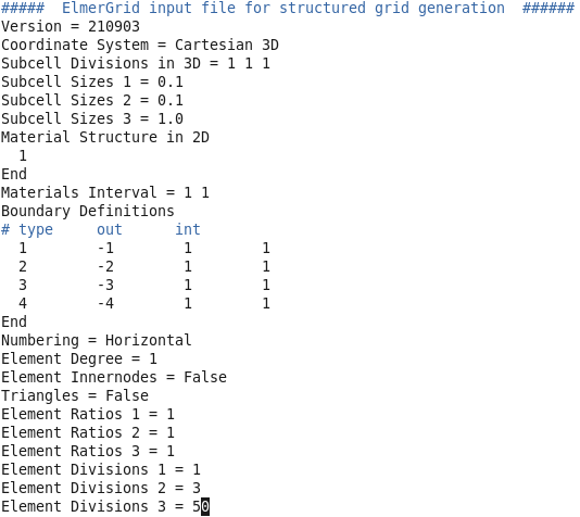
A proper description of the problem mesh requires a good level of understanding of finite element method, which is beyond the purpose of this page. For more information about ElmerGrid and finite element methods, visit this document.
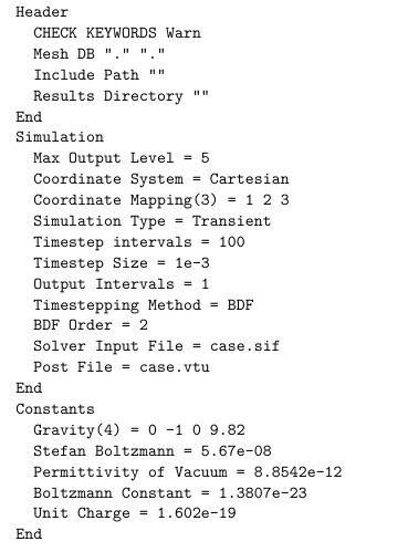
The ".sif" file uses a keyword-pair format to describe the rest of the problem outside of the description. Each keyword can be thought of as a command to the Elmer solver which describes one particular feature of the problem. Many of these commands require parameters to be passed by user; these parameters are defined in front of the command after the "=" symbol. The first section of SIF file defines general settings of the problem as well as the location for geometry file, where to save simulation results, the type of simulation, time step used, etc. The definitions within this section of the SIF file are very straight-foward, as shown in the following file capture:
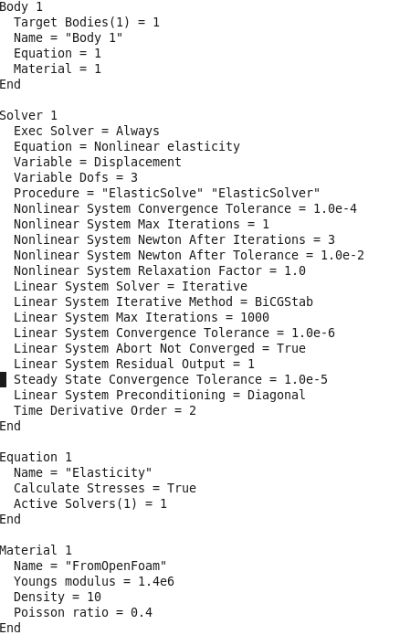
In the next section, the types of equations to be solved and the material properties for each constituent are described. Depending on the type of solver needed, a series of solver-related parameters should be passed to Elmer. The following example defines a non-linear elasticity solver for Elmer, along with the type of equation solver and non-linear solution strategies that should be utilized in solving the problem.
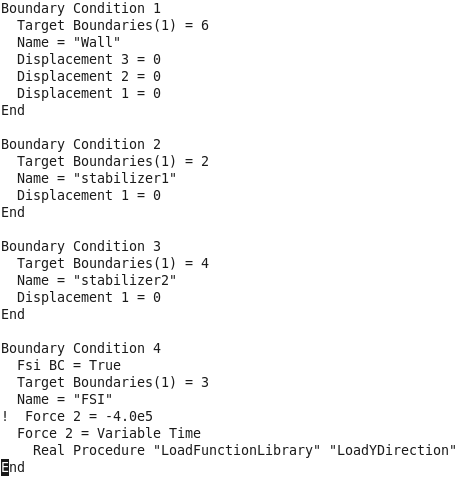
The remainder of the SIF file defines the boundary conditions of the problem. For a structural problem, different types of boundary conditions can be used including conditions for displacement and traction. Boundary condition definition starts with a Target Boundaries(x) = y statement, where x is an integer and y values are separated by space (if more than one is provided), that specifies how many boundaries are using this description and which boundary within the geometry file should be used. Finally, we specify which direction our loads/displacement should be applied (here 1, 2, and 3 correspond to X, Y, and Z directions). Some boundary conditions require special treatments that are defined by additional keywords. For example, boundary condition 4 within the Sample SIF file III figure describes an FSI boundary. In this case, we tell Elmer to apply a variable force to the sections of the geometry that reside on this boundary.
We must also specify, (1) which direction loads should be applied, (2) whether these loads are variable in time, and (3) if Elmer should resort to function LoadYDirection in LoadFunctionLibrary when it is needed. Special attention must be paid to proper formating; further definition of and information about the keywords can be found within the Elmer manuals.
Elmerfoam uses OpenFOAM as its fluid solver module to solve for fluid pressure and velocity. To properly capture deformations in the solid/fluid interface, OpenFOAM must also perform mesh update and re-meshing procedures to maintain the quality of the computational grid during the simulation (in a fluid problem, the grid is equivalent to a mesh for solid problems). OpenFOAM uses a finite-volume discretization scheme to obtain pressures and velocities and a Laplace solver to perform the re-meshing tasks. The user must specify proper parameters for these solvers in the input files.
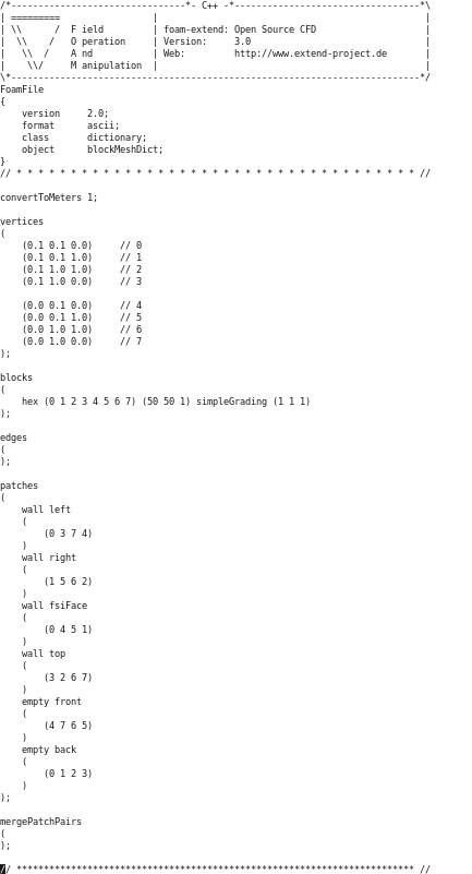
The definition of a problem in OpenFOAM is performed via multi-part input file strategy. For FSI problems, OpenFOAM requires both the definition of the solid and the fluid sections of the grid. In ElmerFoam, however, the solid definition for OpenFOAM is disregarded and is replaced with the definition from Elmer. Similarly, all other computations for the solid section are performed solely by Elmer. To setup a fluid problem in , we must follow a strict folder/file hierarchy because OpenFOAM searches for the definition of a problem within multiple files, all of which reside in a set of subfolders. The input files in OpenFOAM are also referred to as dictionary files. In each dictionary file, a set of keyword-value pairs specify proper settings for part of the problem and solution procedure. There should be at-least three major sub-folders within the main fluid problem definition folder, /fluid/. These sub-folders are first, ./fluid/0/, second, ./fluid/constant/, and third, ./fluid/system/. We will briefly describe each folder and its contents; readers are strongly encouraged to resort to OpenFOAM's documentation for more details.
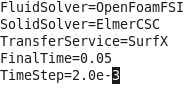
Currently, ElmerFoamFSI uses a very basic input file (named test.config). This file should reside in the ./fluid/ folder where the ElmerFoamFSI executable is called, and should be passed to the executable as a command-line parameter. The following example shows the structure of this keyword-value pair file; in this example, the name of fluid and structure solver modules are specified in the first two lines. The third line specifies the solution transfer module (in this case, SurfX, which is a part of IMPACT). The rest of the file describes the total analysis time and the time step.
There are multiple example problems ElmerFoamFSI can simulate, grouped into two broad categories: simple static problems and simple dynamic problems.
Problem-specific directions are found through the following links:
Here are the directions for the Simple Dynamic Problem.
Here are the directions for the Simple Static Problem.
Here are the directions for the Hron-Turek Problem.
 1.8.5
1.8.5 
