 |
NEMoSys
0.63.0
A modular, extensible resource with robust automated mesh generation, mesh quality analysis, adaptive mesh refinement, and data transfer between arbitrary meshes.
|


|
|
NEMoSys
0.63.0
A modular, extensible resource with robust automated mesh generation, mesh quality analysis, adaptive mesh refinement, and data transfer between arbitrary meshes.
|
|
NucMesh is specifically designed to generate meshes for nuclear reactors. It features the capability to quickly create arrays (rectangular, polar, and hexagonal) made up of custom objects, such as circles, polygons, or other arrays.
NucMesh allows the user to efficiently specify, save, create arrays of, and mesh elementary shapes such as circles and regular polygons. It is designed to create 2D meshes, but also has the capability to extrude meshes into 3D space.
The reference page contains information on the parameters used in NucMesh input files.
All NucMesh JSON input files start in the same way:
{
  "Program Type": "NucMesh Generation",
  "Mesh File Options": {
    "Output Mesh File": "mesh_name.vtu"
  },
The "Program Type" is set to "NucMesh Generation" and the mesh file to be created is named. Note that the output mesh file might be VTK or EXODUS II format.
Next, NucMesh-specific options are provided in the "NucMesh Options" section. "Saved Objects" may be any kind of shape or array of shapes.
  "NucMesh Options": {
    "Saved Objects": [
      {
        "Name":
        "Type":
        ...
      }
    ],
    "Shapes": [
      {
        "Type":
        ...
      }
    ],
    "Extrude": []
  }
These tutorials are designed to gently lead a new user through the current capabilities of NucMesh.
To create a circle, at least one radius must be specified. This is done within the "Rings" block, which makes it easy to add as many concentric circles as needed, each with their own mesh type, material, or sideset. For example, this input produces a circular triangular mesh with a radius of 5 units.
{
  "Program Type": "NucMesh Generation",
  "Mesh File Options": {"Output Mesh File": "simple_circles.vtu"},
  "NucMesh Options": {
    "Shapes": [
      {"Type": "Circles", "Rings": [{"Radius": 5, "Mesh": {"Type": "T"}}]}
    ]
  }
}
To add another circle, another radius and mesh type are added within the "Rings" array:
{
  "Program Type": "NucMesh Generation",
  "Mesh File Options": {"Output Mesh File": "circles.vtu"},
  "NucMesh Options": {
    "Shapes": [
      {"Type": "Circles", "Rings": [{"Radius": 4, "Mesh": {"Type": "T"}},
                                    {"Radius": 5, "Mesh": {"Type": "T"}}]}
    ]
  }
}
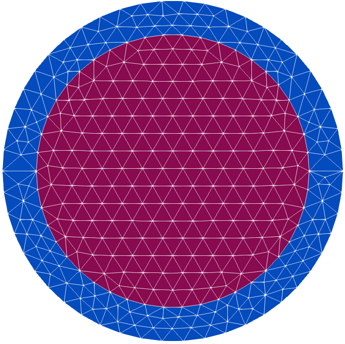
Note that the new circle, which has a radius of 4, is added above the initial circle. NucMesh expects radii to be listed in increasing order–doing otherwise will result in an error.
material types, discerning the border of the inner circle is a little difficult." width=400
Looking closely at the mesh shown above, you can see that there is indeed a ring and two distinct circles. However, without different material types, Paraview does not perceive them as different entities. To make it a little clearer, we can assign different materials to the two rings:
{
  "Program Type": "NucMesh Generation",
  "Mesh File Options": {"Output Mesh File": "circles.vtu"},
  "NucMesh Options": {
    "Shapes": [
      {"Type": "Circles", "Rings": [{"Radius": 4, "Mesh": {"Type": "T"}, "Material": "A"},
                                    {"Radius": 5, "Mesh": {"Type": "T"}, "Material": "B"}]}
    ]
  }
}
Let's add a few more circles–instead of concentric, let's try adding three small circles within the smaller circle. To specify a center that isn't just the default of [0, 0, 0], we add the "Center" keyword to place each small circle 2 units away from the center:
{
  "Program Type": "NucMesh Generation",
  "Mesh File Options": {"Output Mesh File": "circles.vtu"},
  "NucMesh Options": {
    "Shapes": [
      {"Type": "Circles", "Rings": [{"Radius": 4, "Mesh": {"Type": "T"}, "Material": "A"},
                                    {"Radius": 5, "Mesh": {"Type": "T"}, "Material": "B"}]},
      {"Type": "Circles", "Center": [0, 2, 0], "Rings":[ {"Radius": 1, "Mesh": {"Type": "T"}, "Material": "C"}]},
      {"Type": "Circles", "Center": [1.732050808, -1, 0], "Rings":[ {"Radius": 1, "Mesh": {"Type": "T"}, "Material": "C"}]},
      {"Type": "Circles", "Center": [-1.732050808, -1, 0], "Rings":[ {"Radius": 1, "Mesh": {"Type": "T"}, "Material": "C"}]}
    ]
  }
}
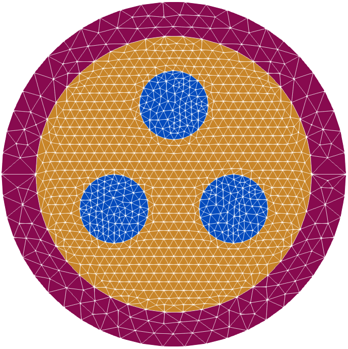
Since each of the smallest circles has a different center, they must be added individually. A later tutorial will introduce polar arrays, which allow the user to very quickly create the same configuration, without requiring the user to manually calculate each circle's center and add them manually.
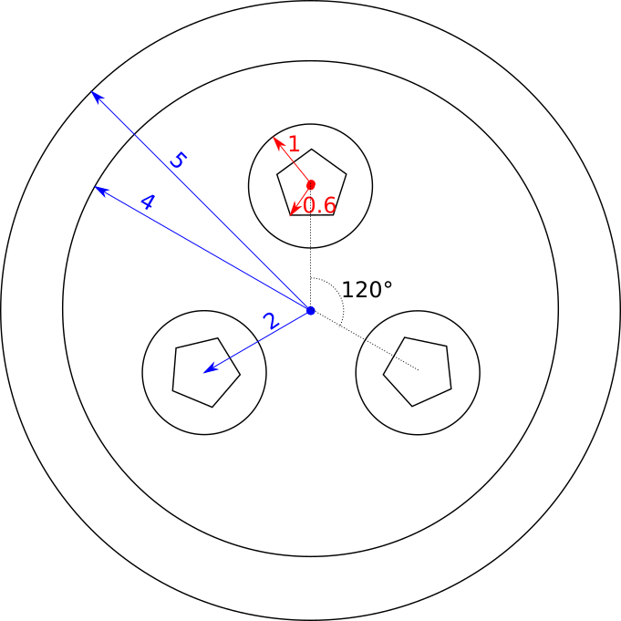
To create polygon shapes, "Circles And Polys" is used as the shape's "Type". This requires a few more parameters than for circle specification: the type of polygon is determined with the "Number of Sides" keyword, and within the "Rings" section, a "Shape Type" (which may be "Circle" or "Poly") must be specified. Note that the number of sides is specified outside of the "Rings" section, because only one type of polygon can be used within a "Circles And Polys" object. To give the size of the polygon, the "Radius" keyword is used, and refers to the radius of the circumscribing circle.
As an example, let's add a polygon inside each of the three smallest circles:
{
  "Program Type": "NucMesh Generation",
  "Mesh File Options": {"Output Mesh File": "circles.vtu"},
  "NucMesh Options": {
    "Shapes": [
      {
        "Type": "Circles", "Rings": [{"Radius": 4, "Mesh": {"Type": "T"}, "Material": "A"},
                                    {"Radius": 5, "Mesh": {"Type": "T"}, "Material": "B"}]
      },
      {
        "Type": "Circles And Polys",
        "Center": [0, 2, 0],
        "Number of Sides": 5,
        "Rings":[{"Shape Type": "Poly", "Radius": 0.6, "Mesh": {"Type": "T"}, "Material": "D"},
                 {"Shape Type": "Circle", "Radius": 1, "Mesh": {"Type": "T"}, "Material": "C"}]
      },
      {
        "Type": "Circles And Polys",
        "Center": [1.732050808, -1, 0],
        "Number of Sides": 5,
        "Rings":[{"Shape Type": "Poly", "Radius": 0.6, "Mesh": {"Type": "T"}, "Material": "D"},
                 {"Shape Type": "Circle", "Radius": 1, "Mesh": {"Type": "T"}, "Material": "C"}]
      },
      {
        "Type": "Circles And Polys",
        "Center": [-1.732050808, -1, 0],
        "Number of Sides": 5,
        "Rings":[{"Shape Type": "Poly", "Radius": 0.6, "Mesh": {"Type": "T"}, "Material": "D"},
                 {"Shape Type": "Circle", "Radius": 1, "Mesh": {"Type": "T"}, "Material": "C"}]
      }
    ]
  }
}
Note that again, the new shapes are added above the exiting once since they have a smaller radius.
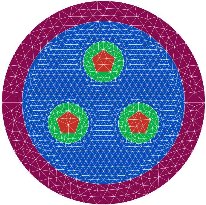
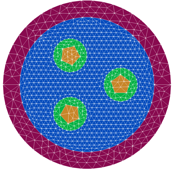
Each pentagon is oriented with the flat side at the bottom. Until now, all the shapes have been circles and therefore their orientation hasn't been a concern. Now, to ensure radial symmetry, the second and third polygons will be rotated:
{
  "Program Type": "NucMesh Generation",
  "Mesh File Options": {"Output Mesh File": "circles.vtu"},
  "NucMesh Options": {
    "Shapes": [
      {"Type": "Circles", "Rings": [{"Radius": 4, "Mesh": {"Type": "T"}, "Material": "A"},
                                    {"Radius": 5, "Mesh": {"Type": "T"}, "Material": "B"}]},
      {"Type": "Circles And Polys",
       "Center": [0, 2, 0],
       "Number of Sides": 5,
       "Rings":[{"Shape Type": "Poly", "Radius": 0.6, "Mesh": {"Type": "T"}, "Material": "D"},
                {"Shape Type": "Circle", "Radius": 1, "Mesh": {"Type": "T"}, "Material": "C"}]},
      {"Type": "Circles And Polys",
       "Center": [1.732050808, -1, 0],
       "Number of Sides": 5,
       "Rings":[{"Shape Type": "Poly", "Radius": 0.6, "Mesh": {"Type": "T"}, "Rotation": -60, "Material": "D"},
                {"Shape Type": "Circle", "Radius": 1, "Mesh": {"Type": "T"}, "Material": "C"}]},
      {"Type": "Circles And Polys",
       "Center": [-1.732050808, -1, 0],
       "Number of Sides": 5,
       "Rings":[{"Shape Type": "Poly", "Radius": 0.6, "Mesh": {"Type": "T"}, "Rotation": 60, "Material": "D"},
                {"Shape Type": "Circle", "Radius": 1, "Mesh": {"Type": "T"}, "Material": "C"}]}
    ]
  }
}
For a few simple shapes, calculating positions and rotation angles is not too difficult. However, if design changes required that there be seven circles, each with a seven-sided polygon inside, recalculating and updating all the required values and copy-pasting new shapes could quickly become onerous.
Arrays, which can be rectangular, polar, or hexagonal, technically fall under the category of "Shapes" in NucMesh. Each type of array has its own parameter requirements, but all three require a list of shapes that are present in the array and a specification for the pattern.
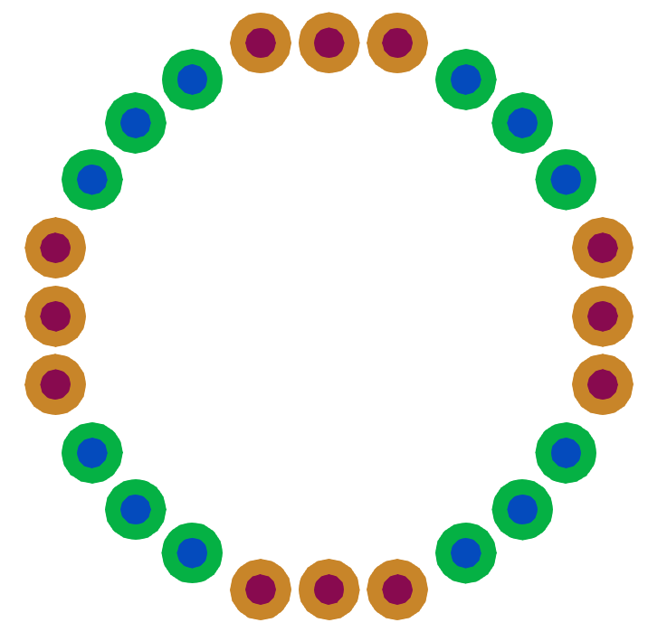
We can replace the three "Circles And Polys" shapes with a single polar array. Instead of calculating each small circle's center individually, we can omit the "Center" keyword entirely, and let the default center of [0, 0, 0] be used. Setting the "Radius" to 2 will place each array object 2 units away from the center, with no trigonometry required. Since we want the small circles evenly spaced around the entire circle, we specify a "Start Angle" of 0 degrees and an "End Angle" of 360 degrees. To get the pentagons to rotate with the array and maintain radial symmetry, we set "Rotate with Array" to true.
The "Pattern" for a polar array is set with a 1D array. In this case, we use [0, 0, 0] to indicate that we want three of the first (zero indexed) shape listed to be evenly spaced between the "Start Angle" and the "End Angle". Since only one shape is being used in the polar array, only one needs to be listed.
{
  "Program Type": "NucMesh Generation",
  "Mesh File Options": {"Output Mesh File": "circles.vtu"},
  "NucMesh Options": {
    "Shapes": [
      {"Type": "Circles", "Rings": [{"Radius": 4, "Mesh": {"Type": "T"}, "Material": "A"},
                                    {"Radius": 5, "Mesh": {"Type": "T"}, "Material": "B"}]},
      {"Type": "Polar Array",
       "Radius": 2,
       "Pattern": [0, 0, 0],
       "Start Angle": 0,
       "End Angle": 360,
       "Rotate with Array": true,
       "Shapes": [
         {"Type": "Circles And Polys",
          "Center": [0, 0, 0],
          "Number of Sides": 5,
          "Rings":[{"Shape Type": "Poly", "Radius": 0.6, "Mesh": {"Type": "T"}, "Material": "D"},
                   {"Shape Type": "Circle", "Radius": 1, "Mesh": {"Type": "T"}, "Material": "C"}]}
        ]
      }
    ]
  }
}
The mesh pictured above is not quite the same as the one created manually. NucMesh measures angles from the positive x axis, so setting the "Start Angle" to 0 means that the first "Circles And Polys" object is placed there, instead of at 90 degrees. To fix this, we can change the "Start Angle" and the "End Angle" to 90 degrees and 450 degrees (note that entering 90 degrees here is also totally acceptable):
{
  "Program Type": "NucMesh Generation",
  "Mesh File Options": {"Output Mesh File": "circles.vtu"},
  "NucMesh Options": {
    "Shapes": [
      {"Type": "Circles", "Rings": [{"Radius": 4, "Mesh": {"Type": "T"}, "Material": "A"},
                                    {"Radius": 5, "Mesh": {"Type": "T"}, "Material": "B"}]},
      {"Type": "Polar Array",
       "Radius": 2,
       "Pattern": [0, 0, 0],
       "Start Angle": 90,
       "End Angle": 450,
       "Rotate with Array": true,
       "Shapes": [
         {"Type": "Circles And Polys",
          "Center": [0, 0, 0],
          "Number of Sides": 5,
          "Rings":[{"Shape Type": "Poly", "Radius": 0.6, "Mesh": {"Type": "T"}, "Material": "D"},
                   {"Shape Type": "Circle", "Radius": 1, "Mesh": {"Type": "T"}, "Material": "C"}]}
        ]
      }
    ]
  }
}
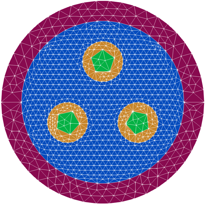
of the smaller circles but not the orientation of the polygons within them." width=400
The smallest circles are now correctly positioned, but the pentagons within them are not aligned as expected. To get the correct position, the polygon must be oriented so that it is correct relative to the original 0 degree–in this case, we can simply negate the rotation imposed by changing the starting angle by simply setting the "Poly" object's rotation to -90 degrees.
{
  "Program Type": "NucMesh Generation",
  "Mesh File Options": {"Output Mesh File": "circles.vtu"},
  "NucMesh Options": {
    "Shapes": [
      {"Type": "Circles", "Rings": [{"Radius": 4, "Mesh": {"Type": "T"}, "Material": "A"},
                                    {"Radius": 5, "Mesh": {"Type": "T"}, "Material": "B"}]},
      {"Type": "Polar Array",
       "Radius": 2,
       "Pattern": [0, 0, 0],
       "Start Angle": 90,
       "End Angle": 90,
       "Rotate with Array": true,
       "Shapes": [
         {"Type": "Circles And Polys",
          "Center": [0, 0, 0],
          "Number of Sides": 5,
          "Rings":[{"Shape Type": "Poly", "Radius": 0.6, "Mesh": {"Type": "T"}, "Rotation": -90, "Material": "D"},
                   {"Shape Type": "Circle", "Radius": 1, "Mesh": {"Type": "T"}, "Material": "C"}]}
        ]
      }
    ]
  }
}
Once the "Circles And Polys" object is positioned correctly, the "Rotate with Array" setting ensures that each repeated object is also oriented correctly.
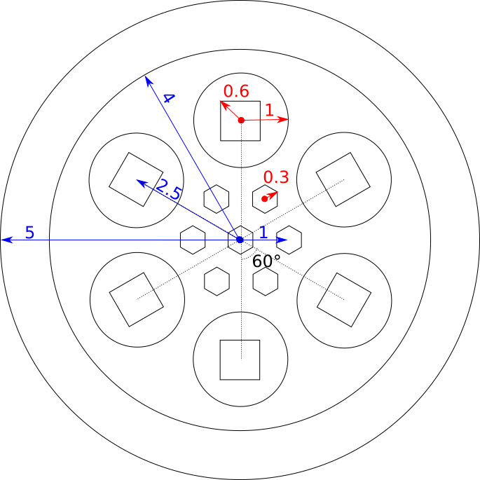
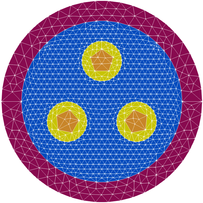
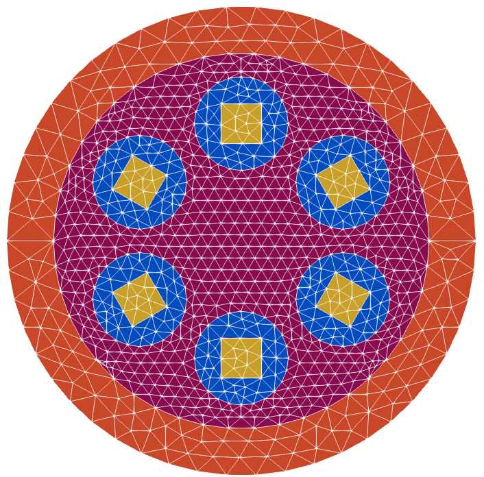
Now that we have a convenient array of objects, let's change some parameters: change the number of small circles to six and the polygon inside to a square. To fit the additional circles, we'll also expand the polar array radius to 2.5:
{
  "Program Type": "NucMesh Generation",
  "Mesh File Options": {"Output Mesh File": "circles.vtu"},
  "NucMesh Options": {
    "Shapes": [
      {"Type": "Circles", "Rings": [{"Radius": 4, "Mesh": {"Type": "T"}, "Material": "A"},
                                    {"Radius": 5, "Mesh": {"Type": "T"}, "Material": "B"}]},
      {"Type": "Polar Array",
       "Radius": 2.5,
       "Pattern": [0, 0, 0, 0, 0, 0],
       "Start Angle": 90,
       "End Angle": 450,
       "Rotate with Array": true,
       "Shapes": [
         {"Type": "Circles And Polys",
          "Center": [0, 0, 0],
          "Number of Sides": 4,
          "Rings":[{"Shape Type": "Poly", "Radius": 0.6, "Mesh": {"Type": "T"}, "Rotation": -90, "Material": "D"},
                   {"Shape Type": "Circle", "Radius": 1, "Mesh": {"Type": "T"}, "Material": "C"}]}
        ]
      }
    ]
  }
}
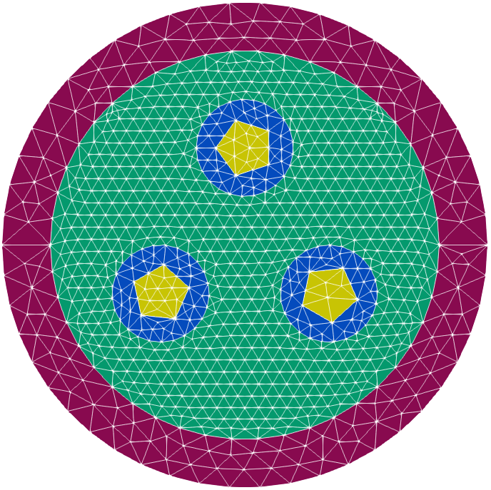
We can fill the middle of the larger circles with a hexagonal array of hexagons, which we will rotate by 30 degrees:
{
  "Program Type": "NucMesh Generation",
  "Mesh File Options": {"Output Mesh File": "circles.vtu"},
  "NucMesh Options": {
    "Shapes": [
      {"Type": "Circles", "Rings": [{"Radius": 4, "Mesh": {"Type": "T"}, "Material": "A"},
                                    {"Radius": 5, "Mesh": {"Type": "T"}, "Material": "B"}]},
      {"Type": "Polar Array",
       "Radius": 2.5,
       "Pattern": [0, 0, 0, 0, 0, 0],
       "Start Angle": 90,
       "End Angle": 450,
       "Rotate with Array": true,
       "Shapes": [
         {"Type": "Circles And Polys",
          "Center": [0, 0, 0],
          "Number of Sides": 4,
          "Rings":[{"Shape Type": "Poly", "Radius": 0.6, "Mesh": {"Type": "T"}, "Rotation": -90, "Material": "D"},
                   {"Shape Type": "Circle", "Radius": 1, "Mesh": {"Type": "T"}, "Material": "C"}]}
          ]
        },
        {"Type": "Hexagonal Array",
         "Grid Distance": 1,
         "Pattern": [[0,0],[0,0,0],[0,0]],
         "Shapes": [
            {"Type": "Circles And Polys",
             "Center": [0, 0, 0],
             "Number of Sides": 6,
             "Rings": [{"Shape Type": "Poly", "Radius": 0.3, "Mesh": {"Type": "T"}, "Rotation": 30, "Material": "B"}]
            }
          ]
        }
    ]
  }
}
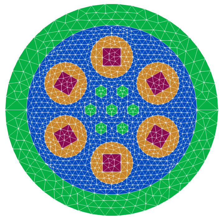
Hexagonal arrays are declared with a 2D array and a grid distance, which specifies the spacing between the centers of the objects in the array. Although the user is able to define their own pattern so that the shape IDs can be placed appropriately, the numbers of rows and columns are restricted to regular hexagonal shapes:
[[0, 0],
 [0, 0, 0],
 [0, 0]]

[[0, 0, 0],
 [0, 0, 0, 0],
 [0, 0, 0, 0, 0]
 [0, 0, 0, 0],
 [0, 0, 0]]

[[0, 0, 0, 0],
 [0, 0, 0, 0, 0],
 [0, 0, 0, 0, 0, 0],
 [0, 0, 0, 0, 0, 0, 0],
 [0, 0, 0, 0, 0, 0],
 [0, 0, 0, 0, 0],
 [0, 0, 0, 0]]
etc., where 0 can be replaced by the index of the desired shape within the array's "Shapes" list.
The two arrays used thus far included only a single shape. To demonstrate how different shapes can be incorporated into arrays, let's introduce rectangular arrays, the third and final array type.
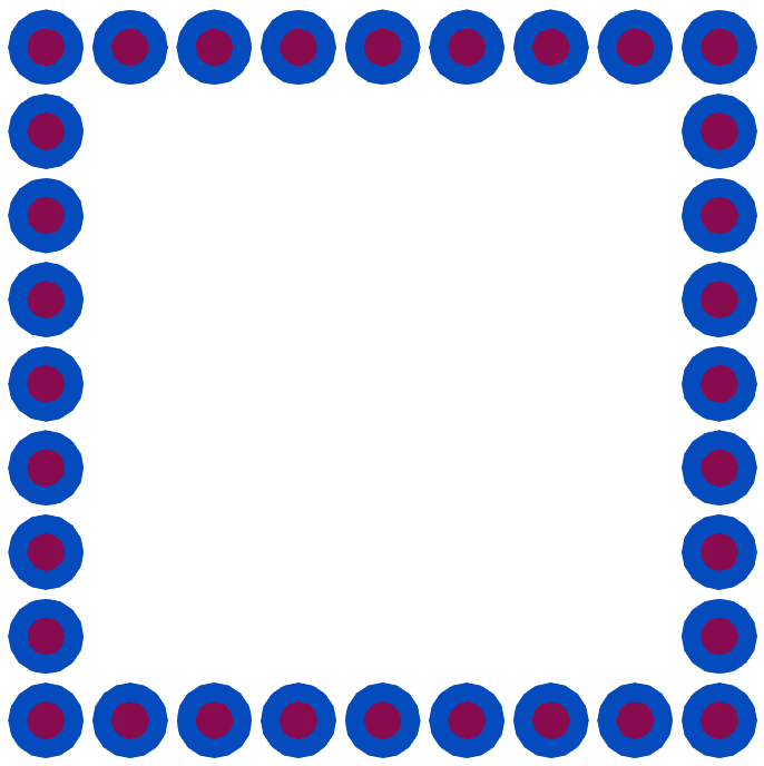
Let's start with an array of circles forming the outline of a square:
{
  "Program Type": "NucMesh Generation",
  "Mesh File Options": {"Output Mesh File": "squoval.vtu"},
  "NucMesh Options": {
    "Shapes": [
      {
        "Type": "Rectangular Array",
        "Grid Distance": [1, 1],
        "Pattern": [[1, 1, 1, 1, 1, 1, 1, 1, 1],
                    [1, 0, 0, 0, 0, 0, 0, 0, 1],
                    [1, 0, 0, 0, 0, 0, 0, 0, 1],
                    [1, 0, 0, 0, 0, 0, 0, 0, 1],
                    [1, 0, 0, 0, 0, 0, 0, 0, 1],
                    [1, 0, 0, 0, 0, 0, 0, 0, 1],
                    [1, 0, 0, 0, 0, 0, 0, 0, 1],
                    [1, 0, 0, 0, 0, 0, 0, 0, 1],
                    [1, 1, 1, 1, 1, 1, 1, 1, 1]],

          "Shapes": [
          null,
          {
            "Type": "Circles",
            "Rings": [{"Radius": 0.225, "Mesh": {"Type":"T"}, "Material": "A"},
                      {"Radius": 0.45, "Mesh": {"Type":"T"}, "Material": "B"}]
          }
        ]
      }
    ]
  }
}
Rectangular arrays only require specification of a grid distance (the distance between the centers of adjacent points). Unlike for hexagonal arrays, it is possible to specify a different distance in the x- and y-directions, so a JSON array is used instead of a single value. Rectangular arrays use a 2D array of arrays to specify the pattern.
Note that in this pattern, we use two different shapes. Because null is the first in the array's Shapes list, its index is 0. Every 0 in the pattern thus corresponds to null, meaning that no shape will be placed there. The second object in the array's Shapes list is a circle with two rings, and its index is 1.
Say we want the corners of the square to be more rounded. We'll additionally add a third shape (identical to the second shape, except with different materials) and change the straight edges in the pattern to 2:
{
  "Program Type": "NucMesh Generation",
  "Mesh File Options": {"Output Mesh File": "squoval.vtu"},
  "NucMesh Options": {
    "Shapes": [
      {
        "Type": "Rectangular Array",
        "Grid Distance": [1, 1],
        "Pattern": [[0, 0, 1, 2, 2, 2, 1, 0, 0],
                    [0, 1, 0, 0, 0, 0, 0, 1, 0],
                    [1, 0, 0, 0, 0, 0, 0, 0, 1],
                    [2, 0, 0, 0, 0, 0, 0, 0, 2],
                    [2, 0, 0, 0, 0, 0, 0, 0, 2],
                    [2, 0, 0, 0, 0, 0, 0, 0, 2],
                    [1, 0, 0, 0, 0, 0, 0, 0, 1],
                    [0, 1, 0, 0, 0, 0, 0, 1, 0],
                    [0, 0, 1, 2, 2, 2, 1, 0, 0]],

          "Shapes": [
          null,
          {
            "Type": "Circles",
            "Rings": [{"Radius": 0.225, "Mesh": {"Type":"T"}, "Material": "A"},
                      {"Radius": 0.45, "Mesh": {"Type":"T"}, "Material": "B"}]
          },
          {
            "Type": "Circles",
            "Rings": [{"Radius": 0.225, "Mesh": {"Type":"T"}, "Material": "C"},
                      {"Radius": 0.45, "Mesh": {"Type":"T"}, "Material": "D"}]
          }
        ]
      }
    ]
  }
}
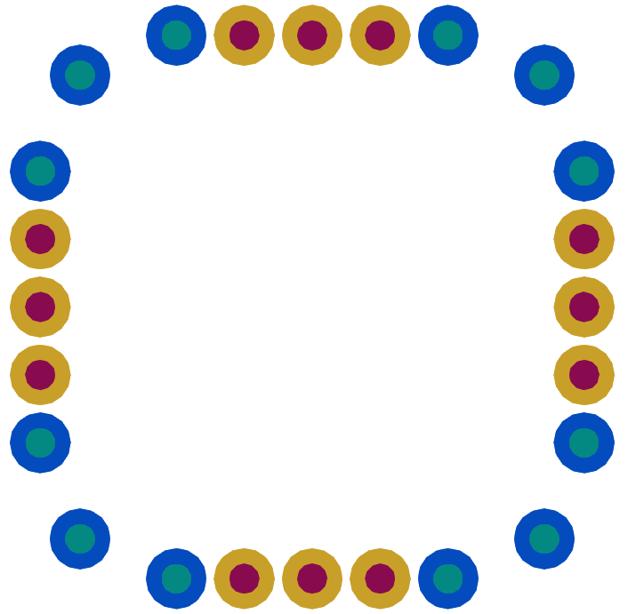
With a smaller rectangular array, making smooth curves is impossible. Additionally, the grid doesn't allow the space between objects to be the same along diagonal and cardinal sides. We could create a much larger rectangular array, which would make differences in spacing less obvious and allow us to form a better curve, but entering in hundreds of integers to define the pattern would get tedious very quickly.
Instead, let's use polar arrays to specify the corners. To make this easier, we'll introduce Saved Objects, which allow us to define a shape or array, name it, and use it later.
{
  "Program Type": "NucMesh Generation",
  "Mesh File Options": {"Output Mesh File": "squoval.vtu"},
  "NucMesh Options": {
    "Saved Objects":[
      {
        "Name": "circleAB",
        "Type": "Circles",
        "Rings": [{"Radius": 0.225, "Mesh": {"Type":"T"}, "Material": "A"},
                  {"Radius": 0.45, "Mesh": {"Type":"T"}, "Material": "B"}]
      },
      {
        "Name": "circleCD",
        "Type": "Circles",
        "Rings": [{"Radius": 0.225, "Mesh": {"Type":"T"}, "Material": "C"},
                  {"Radius": 0.45, "Mesh": {"Type":"T"}, "Material": "D"}]
      }
    ],
    "Shapes": [
      {
        "Type": "Rectangular Array",
        "Grid Distance": [1, 1],
        "Pattern": [[0, 0, 0, 1, 1, 1, 0, 0, 0],
                    [0, 0, 0, 0, 0, 0, 0, 0, 0],
                    [0, 0, 0, 0, 0, 0, 0, 0, 0],
                    [1, 0, 0, 0, 0, 0, 0, 0, 1],
                    [1, 0, 0, 0, 0, 0, 0, 0, 1],
                    [1, 0, 0, 0, 0, 0, 0, 0, 1],
                    [0, 0, 0, 0, 0, 0, 0, 0, 0],
                    [0, 0, 0, 0, 0, 0, 0, 0, 0],
                    [0, 0, 0, 1, 1, 1, 0, 0, 0]],

          "Shapes": [
          null,
          {"Saved Object": "circleCD"}
        ]
      },
      {
        "Type": "Polar Array",
        "Start Angle": -15,
        "End Angle": 345,
        "Radius": 4,
        "Pattern": [0, 0, 0, 1, 1, 1, 0, 0, 0, 1, 1, 1, 0, 0, 0, 1, 1, 1, 0, 0, 0, 1, 1, 1],
        "Shapes": [
          null,
          {"Saved Object": "circleAB"}
        ]
      }
    ]
  }
}
Note that the rectangular array's pattern has been changed–the corners have been set to null and the index of the edges has been set to 1. This still corresponds to the same shape, but now it is second in the list of shapes instead of third.
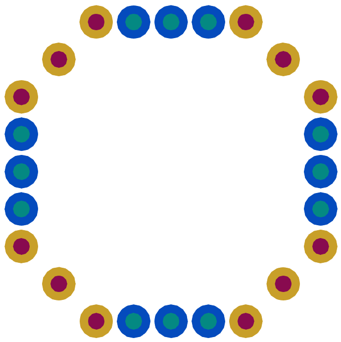
The spacing in the above image is much improved, but the corners are so rounded that the entire shape looks like a circle. Ideally, the angle between the adjacent objects in the straight edges and corners should be zero, but this will require four polar arrays, similar to what is shown below:
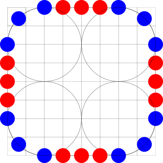
Corners will be represented with polar arrays. Polar arrays are designed to work nicely for full circles, which makes the end angle behave a little unexpectedly for incomplete arcs. For example, if we want a polar array that starts at 0 degrees and ends at 360 degrees, with a pattern of [0, 1, 2, 3], we would expect to see four objects at the cardinal directions–and of course, that is exactly what we get. However, note that this means that object 0 is at 0 degrees, object 1 is at 90 degrees, object 2 is at 180 degrees, and object 3 is at 270 degrees; there is no object at 360 degrees, because the array is designed to overlap with the original object at 0 degrees. Creating incomplete arcs therefore requires a little extra care.
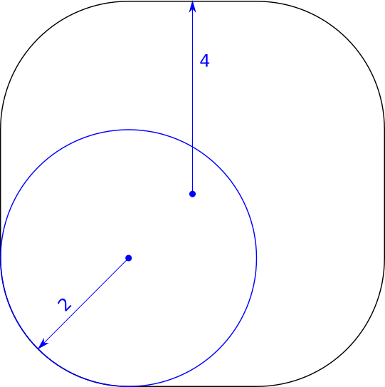
Objects within an array will be \(\frac{end\ angle - start\ angle}{number\ of\ shapes}\) degrees apart. To get three evenly spaced objects in a quarter circle, we need the angle between them to be 45 degrees. Therefore, the end angle that should be used is \((45)(3) + start\ angle\).
To avoid having to manually create four arrays, we can use a single saved array (called "corner" in the input file shown below). This represents the top-right corner. Because our start angle is 0, we set the end angle to 135, as was explained above. After the rectangular array is specified, the saved "corner" object is used four times. The first instance is left unmodified, but for the next three, the Center, Start Angle, and End Angle are overwritten with custom values so that each corner is properly specified.
{
  "Program Type": "NucMesh Generation",
  "Mesh File Options": {"Output Mesh File": "squoval.vtu"},
  "NucMesh Options": {
    "Saved Objects":[
      {
        "Name": "circleAB",
        "Type": "Circles",
        "Rings": [{"Radius": 0.225, "Mesh": {"Type":"T"}, "Material": "A"},
                  {"Radius": 0.45, "Mesh": {"Type":"T"}, "Material": "B"}]
      },
      {
        "Name": "circleCD",
        "Type": "Circles",
        "Rings": [{"Radius": 0.225, "Mesh": {"Type":"T"}, "Material": "C"},
                  {"Radius": 0.45, "Mesh": {"Type":"T"}, "Material": "D"}]
      },
      {
        "Name": "corner",
        "Type": "Polar Array",
        "Center": [2, 2, 0],
        "Start Angle": 0,
        "End Angle": 135,
        "Radius": 2,
        "Pattern": [0, 0, 0],
        "Shapes": [{"Saved Object": "circleAB"}]
      }
    ],
    "Shapes": [
      {
        "Type": "Rectangular Array",
        "Grid Distance": [1, 1],
        "Pattern": [[0, 0, 0, 1, 1, 1, 0, 0, 0],
                    [0, 0, 0, 0, 0, 0, 0, 0, 0],
                    [0, 0, 0, 0, 0, 0, 0, 0, 0],
                    [1, 0, 0, 0, 0, 0, 0, 0, 1],
                    [1, 0, 0, 0, 0, 0, 0, 0, 1],
                    [1, 0, 0, 0, 0, 0, 0, 0, 1],
                    [0, 0, 0, 0, 0, 0, 0, 0, 0],
                    [0, 0, 0, 0, 0, 0, 0, 0, 0],
                    [0, 0, 0, 1, 1, 1, 0, 0, 0]],

          "Shapes": [
          null,
          {"Saved Object": "circleCD"}
        ]
      },
      {"Saved Object": "corner"},
      {"Saved Object": "corner", "Center": [-2, 2, 0], "Start Angle": 90, "End Angle": 225},
      {"Saved Object": "corner", "Center": [-2, -2, 0], "Start Angle": 180, "End Angle": 315},
      {"Saved Object": "corner", "Center": [2, -2, 0], "Start Angle": 270, "End Angle": 405}
    ]
  }
}
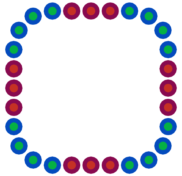
Note that with three circles in the corners, the spacing looks a little too wide. Fortunately, changing to four circles requires only adding an extra 0 to the Pattern and recalculating the End Angles for each of the uses of the "corner" object (+120 from the Start Angles, which will remain the same).
      ...
      {
        "Name": "corner",
        "Type": "Polar Array",
        "Center": [2, 2, 0],
        "Start Angle": 0,
        "End Angle": 120,
        "Radius": 2,
        "Pattern": [0, 0, 0, 0],
        "Shapes": [{"Saved Object": "circleAB"}]
      }
      ...
      {"Saved Object": "corner"},
      {"Saved Object": "corner", "Center": [-2, 2, 0], "Start Angle": 90, "End Angle": 210},
      {"Saved Object": "corner", "Center": [-2, -2, 0], "Start Angle": 180, "End Angle": 300},
      {"Saved Object": "corner", "Center": [2, -2, 0], "Start Angle": 270, "End Angle": 390}
Instead of using a single large and ungainly rectangular array to create the edges, we can create a polar array consisting of four small rectangular arrays. Because NucMesh orients objects relative to the positive x-direction, the array should be entered as a three row, single column 2D array. When placed at 0 degrees, this will form the right vertical edge.
      ...
      {
        "Name": "edge",
        "Type": "Rectangular Array",
        "Grid Distance": [1, 1],
        "Pattern": [[0], [0], [0]],
        "Shapes": [{"Saved Object": "circleAB"}]
      }
      ...
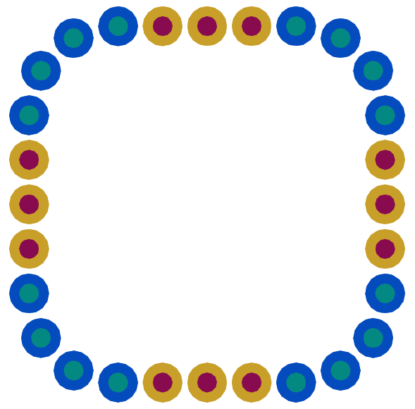
The polar array that places the edges is a simple four element array that forms a complete circle. Rotate with Array is set to true, so the vertical array rotates to place the edges correctly.
{
  "Program Type": "NucMesh Generation",
  "Mesh File Options": {"Output Mesh File": "squoval.vtu"},
  "NucMesh Options": {
    "Saved Objects":[
      {
        "Name": "circleAB",
        "Type": "Circles",
        "Rings": [{"Radius": 0.225, "Mesh": {"Type":"T"}, "Material": "A"},
                  {"Radius": 0.45, "Mesh": {"Type":"T"}, "Material": "B"}]
      },
      {
        "Name": "circleCD",
        "Type": "Circles",
        "Rings": [{"Radius": 0.225, "Mesh": {"Type":"T"}, "Material": "C"},
                  {"Radius": 0.45, "Mesh": {"Type":"T"}, "Material": "D"}]
      },
      {
        "Name": "corner",
        "Type": "Polar Array",
        "Center": [2, 2, 0],
        "Start Angle": 0,
        "End Angle": 120,
        "Radius": 2,
        "Pattern": [0, 0, 0, 0],
        "Shapes": [{"Saved Object": "circleAB"}]
      },
      {
        "Name": "edge",
        "Type": "Rectangular Array",
        "Grid Distance": [1, 1],
        "Pattern": [[0], [0], [0]],
        "Shapes": [{"Saved Object": "circleCD"}]
      }
    ],
    "Shapes": [
      {
        "Type": "Polar Array",
        "Start Angle": 0,
        "End Angle": 360,
        "Radius": 4,
        "Rotate with Array": true,
        "Pattern": [0, 0, 0, 0],
        "Shapes": [{"Saved Object": "edge"}]
      },
      {"Saved Object": "corner"},
      {"Saved Object": "corner", "Center": [-2, 2, 0], "Start Angle": 90, "End Angle": 210},
      {"Saved Object": "corner", "Center": [-2, -2, 0], "Start Angle": 180, "End Angle": 300},
      {"Saved Object": "corner", "Center": [2, -2, 0], "Start Angle": 270, "End Angle": 390}
    ]
  }
}
This 2D mesh can be extruded to create a 3D mesh with the "Extrude" keyword. We can provide an array of values to specify where cell divisions will be made, like so:
{
  "Program Type": "NucMesh Generation",
  "Mesh File Options": {"Output Mesh File": "squoval.vtu"},
  "NucMesh Options": {
    "Saved Objects":[
      {
        ...
      }
    ],
    "Shapes": [
      {
        ...
      }
    ],
    "Extrude": [0.5, 0.5, 0.1]
  }
}
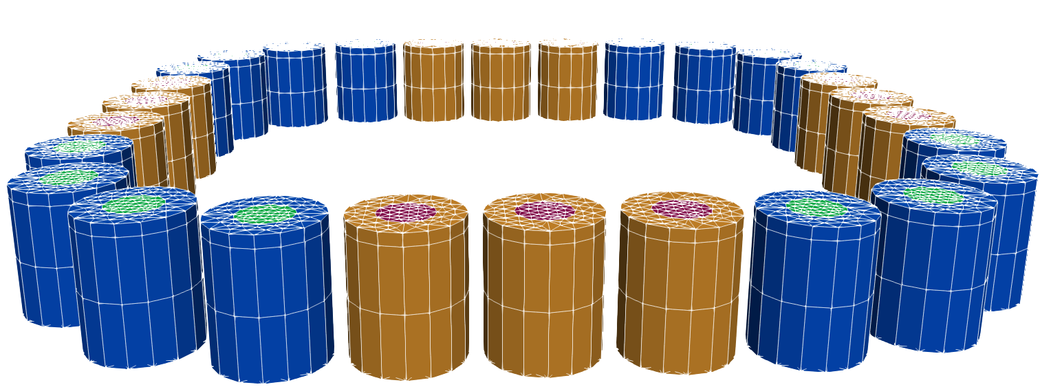
Note that the total height of the extruded mesh will be the sum of the values in the Extrude array.
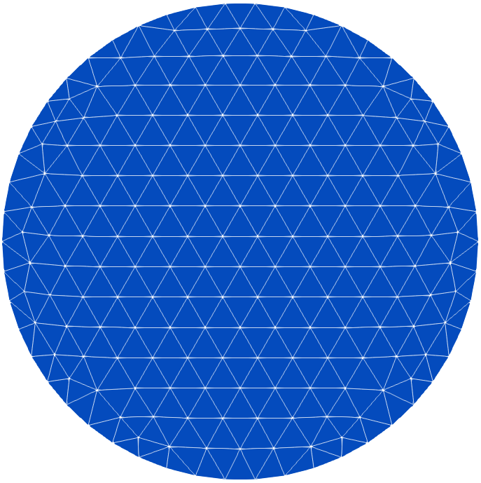
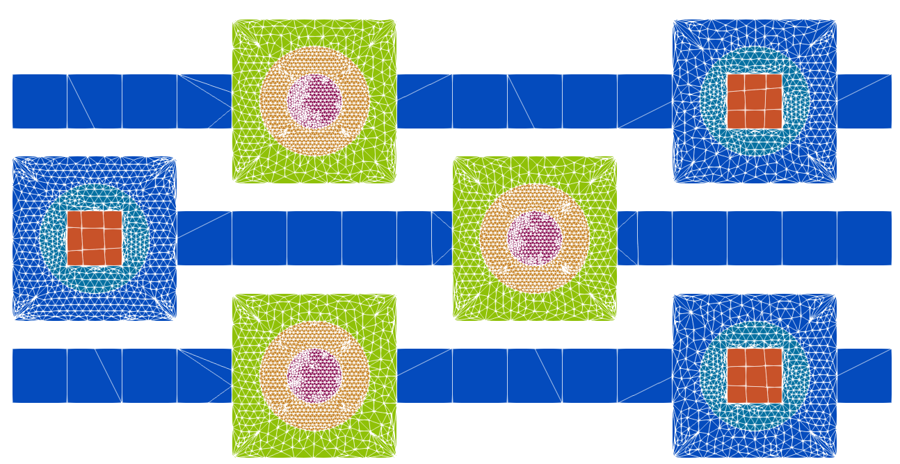
NucMesh offers three meshing options for 2D shapes: triangular, quadrilateral, and structured. To demonstrate how these different mesh types can be used to improve the overall mesh quality, the following input file will be used:
{
  "Program Type": "NucMesh Generation",
  "Mesh File Options": {"Output Mesh File": "mesh_types.vtu"},
  "NucMesh Options": {
    "Saved Objects": [
      {
        "Name": "scc",
        "Type": "Circles And Polys",
        "Number of Sides": 4,
        "Rings": [ {"Shape Type": "Circle", "Radius": 5,"Material": "A", "Mesh": {"Type": "T"}},
                   {"Shape Type": "Circle", "Radius": 10, "Material": "B", "Mesh": {"Type": "T"}},
                   {"Shape Type": "Poly", "Radius": 21.2132034356, "Material": "C", "Mesh": {"Type": "T"}}
                 ]
      },
      {
        "Name": "scs",
        "Type": "Circles And Polys",
        "Number of Sides": 4,
        "Rings": [ {"Shape Type": "Poly", "Radius": 7.07106781187,"Material": "D", "Mesh": {"Type": "T"}},
                   {"Shape Type": "Circle", "Radius": 10, "Material": "E", "Mesh": {"Type": "T"}},
                   {"Shape Type": "Poly", "Radius": 21.2132034356, "Material": "F", "Mesh": {"Type": "T"}}
                 ]
      },
      {
        "Name": "small_square",
        "Type": "Circles And Polys",
        "Number of Sides": 4,
        "Rings": [ {"Shape Type": "Poly", "Radius": 7.07106781187, "Material": "G", "Mesh": {"Type": "T"}} ]
      }
    ],
  "Shapes" : [
    {
      "Type": "Rectangular Array",
      "Grid Distance": [10, 25],
      "Pattern": [[1, 1, 1, 1, 0, 3, 0, 1, 1, 1, 1, 1, 0, 2, 0, 1],
                  [0, 2, 0, 1, 1, 1, 1, 1, 0, 3, 0, 1, 1, 1, 1, 1],
                  [1, 1, 1, 1, 0, 3, 0, 1, 1, 1, 1, 1, 0, 2, 0, 1]],
      "Shapes": [
        null,
        {"Saved Object": "small_square"},
        {"Saved Object": "scs"},
        {"Saved Object": "scc"}
        ]
      }
    ]
  }
}
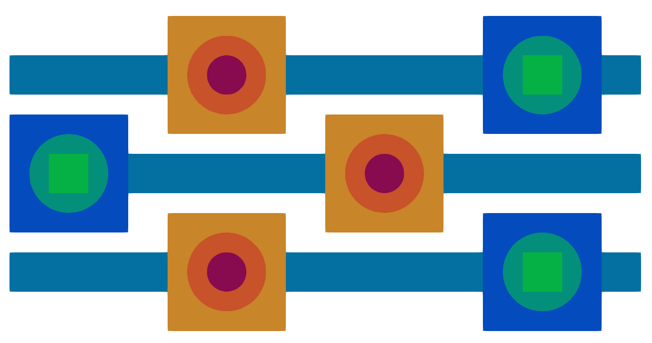
Note that each specified mesh type is "T" (triangular). This results in the following mesh:
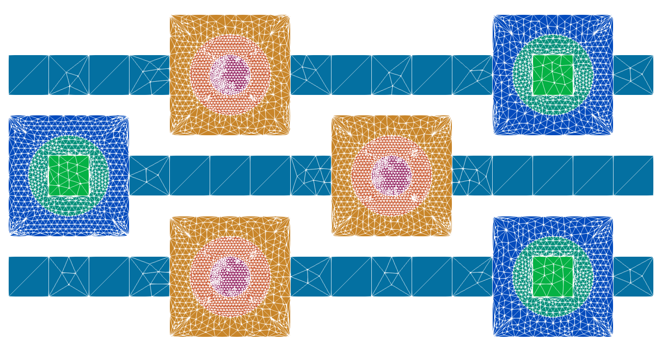
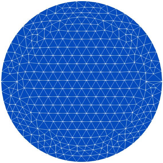
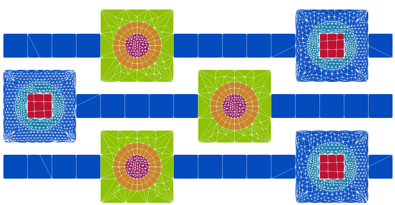
Let's change the smaller square's meshes to type "Q" (quadrilateral).
Structured meshes require an additional parameter; a non-zero integer pair [r, c] must be specified to define the number of elements in the radial and circumferential directions of the shape. Note that the c parameter will represent half the circumference–for 20 elements around the shape, c should be set to 10.
Let's change the middle circle of the object with two concentric circles (named "scc") to a structured mesh with 2 elements in the radial direction and 12 elements in the circumferential directions:
  ...
   {
    "Name": "scc",
    "Type": "Circles And Polys",
    "Number of Sides": 4,
    "Rings": [ {"Shape Type": "Circle", "Radius": 5,"Material": "A", "Mesh": {"Type": "T"}},
               {"Shape Type": "Circle", "Radius": 10, "Material": "B", "Mesh": {"Type": "S", "Number of Elems": [2,6]}},
               {"Shape Type": "Poly", "Radius": 21.2132034356, "Material": "C", "Mesh": {"Type": "T"}}
             ]
  }
  ...
The only rule regarding structured meshes is that they should not be used in the center circle of an object. Let's change the middle ring on the other Circles And Polys object (named "scs") to a structured mesh as well, this time with 10 circumferential elements:
  ...
  {
    "Name": "scs",
    "Type": "Circles And Polys",
    "Number of Sides": 4,
    "Rings": [ {"Shape Type": "Poly", "Radius": 7.07106781187,"Material": "D", "Mesh": {"Type": "Q"}},
               {"Shape Type": "Circle", "Radius": 10, "Material": "E", "Mesh": {"Type": "S", "Number of Elems": [2,5]}},
               {"Shape Type": "Poly", "Radius": 21.2132034356, "Material": "F", "Mesh": {"Type": "T"}}
             ]
  }
  ...
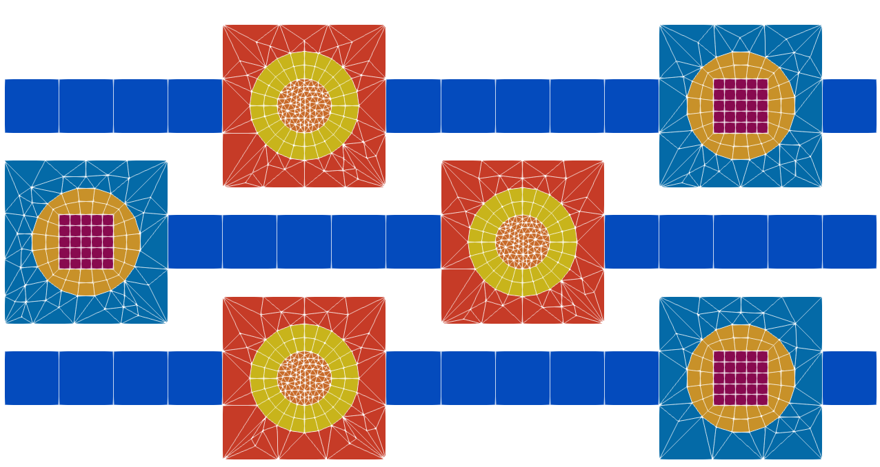
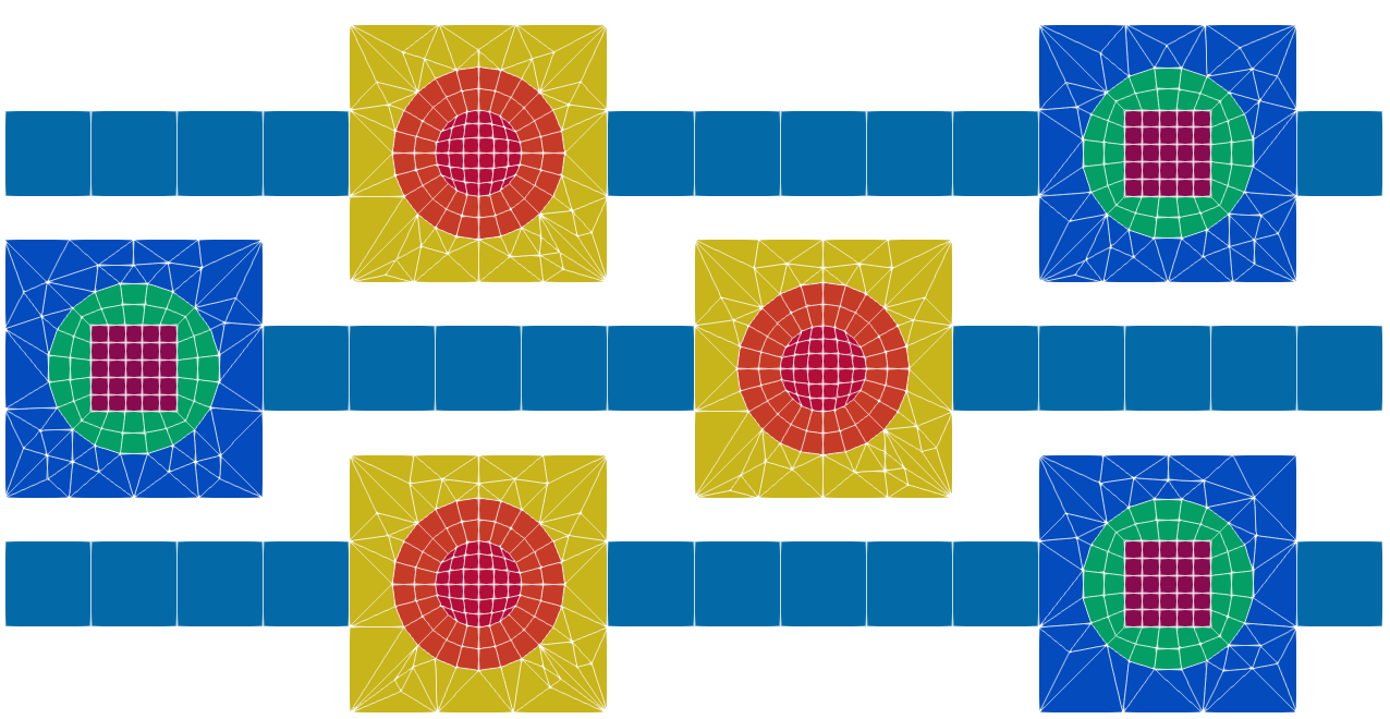
With the structure provided by the structured mesh, a quadrilateral mesh is a good fit for the innermost circle of the "scc" object:
  ...
   {
    "Name": "scc",
    "Type": "Circles And Polys",
    "Number of Sides": 4,
    "Rings": [ {"Shape Type": "Circle", "Radius": 5,"Material": "A", "Mesh": {"Type": "Q"}},
               {"Shape Type": "Circle", "Radius": 10, "Material": "B", "Mesh": {"Type": "S", "Number of Elems": [2,6]}},
               {"Shape Type": "Poly", "Radius": 21.2132034356, "Material": "C", "Mesh": {"Type": "T"}}
             ]
  }
  ...
 1.8.13